


The pump designation is part of API Spec 11AX and describes the main specifications of an API subsurface pump. It is a nomenclature to classify API sucker rod pumps and tubing pumps according to their main characteristics. It is comprised of seven parts, separated by dashes.
Example: 20-125-RHBC-10-4-2-2
Each part, in order, describes the following specifications:
- Nominal tubing size (inch – given as a key representing the actual size)
- Basic bore size (inch)
- Type of pump, type of barrel, location and type of seating assembly (letter code)
- Barrel length (ft)
- Plunger length (ft)
- Length of upper extension, used with heavy-wall barrel (inch)
- Length of lower extension, used with heavy-wall barrel (inch)
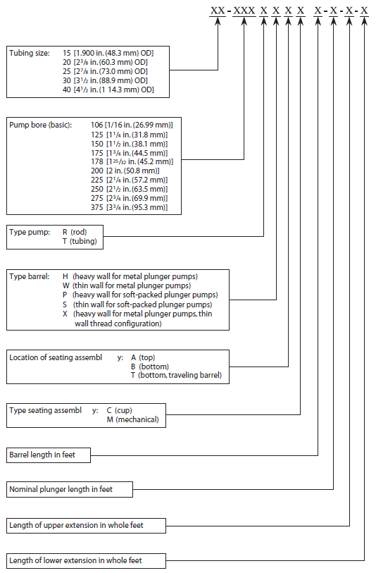
Example: A 1 1⁄4 in. (31.8 mm) bore rod type pump with a 10 ft (3.048 m) heavy wall barrel and 2 ft (0.610 m) upper extension, 2ft (0.610 m) lower extension, a 4 ft (1.219 m) plunger, and a bottom cup type seating assembly for operation in 2 3⁄8 in. (60.3 mm) tubing, would be designated as follows:
20-125 RHBC 10–4–2–2
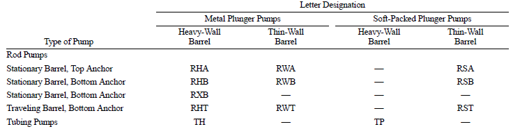
API subsurface pumps are categorized according to the API pump designation. The basic types of pumps and letter designation are shown in the following Table:
Important Properties of API Sucker Rod Pumps:
The field of application of an API subsurface pump is mainly determined by the type of pump, type of barrel and location of the seating assembly. Understanding the advantages and limitations of these specifications is important in selecting the pump best suited for one’s pumping operations.
Here are a few tips you need to know on this matter (API pump designation letter codes given in parenthesis).
Type of Pump:
Rod pump (R) – A rod pump, also called insert pump, is mounted inside the tubing string.
Advantage: Lower service costs compared to tubing pumps, as the pump can be removed by pulling only the rod string.
Limitation: Lower production capacity compared to a tubing pump due to the smaller diameter of the plunger.
Tubing pump (T) – The barrel of a tubing pump is part of the tubing string.
Advantages
- Largest displacement than any rod pump designated for the same tubing size.
- Deployable in wells of all depths due to the rigid design. This robustness is the result of the pump barrel forming a unit with the tubing string.
- Good performance with fluids of higher viscosity as the large size of the plunger leads to a low resistance to flow.
Limitations
- Higher service costs, as the barrel can only be serviced by removing the tubing string.
- Not suited for gassy production fluids because of a large unswept space at the bottom of the stroke resulting in a low compression ratio.
- The larger bore of the tubing pump also means a larger bore acting on the rod string and pumping unit.
Type of Barrel:
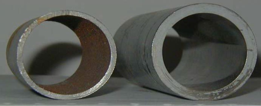
Thin Wall and Heavy Wall Barrels
Heavy wall – 10-12 mm (0.393 – 0.472 in) wall tubing. Externally threaded, allowing the plunger to stroke out at both sides of the pump. The stroke-through construction prevents scale formation inside the barrel. Stronger and more rigid, for greater setting depth.
- With metal plunger (H)
- With soft-packed plunger (P)
Thin wall – 5-7 mm (0.197 – 0.276 in) wall tubing. Internally threaded. Largest bore relative to a given tubing size. For moderate depths.
- With metal plunger (W)
- With soft-packed plunger (S)
Heavy wall with thin-wall thread configuration (X) – 10-12 mm heavy-wall tubing, internally threaded. As the x-type barrel does not require upper and lower extensions like a heavy-wall barrel that could fail under pressure, even greater seating depths are possible.
Location of Seating Assembly:
Top, with stationary barrel (A): Stationary barrel with moving plunger. The anchor (hold-down) is located above the standing valve of the barrel.
Advantages
- Ideally suited for sandy wells as sand is washed away from the seating nipple when fluid is pumped.
- Reduces corrosive attack on the exterior of the barrel.
- Good performance in gassy wells or foamy wells with low fluid levels, when the standing valve is submerged in the fluid. It is recommended to run the pump in combination with a gas anchor.
Limitation
- Not well suited for deep wells, especially if equipped with a thin-wall barrel. This is due to the relatively high differential pressure and the tensile load acting on the barrel during pumping.
Bottom, with stationary barrel (B): Stationary barrel with moving plunger. The anchor (hold-down) is located below the standing valve of the barrel.
Advantages
- Recommended for deep wells as the differential pressure acting on the barrel when pumping fluid is low.
- Appropriate for low static fluid levels as the pump can be seated close to the bottom hole and the relatively large standing valve improves fluid intake.
- Good performance in gassy wells if equipped with a gas anchor. The small height difference between the pump inlet to the standing valve reduces foaming of the fluid.
Limitations
- Not suited in wells with scale formation, as sand and other particles can settle between the tubing wall and barrel.
- Not advisable for intermittent pumping operations, as the barrel can get stuck when solids settle on the plunger.
Bottom, with traveling barrel (T): Moving barrel with stationary plunger. The anchor (hold-down) is located below the standing valve of the plunger.
Advantages
- Ideal in sandy conditions as the moving barrel keeps the fluid in motion, thus reducing the change of sand settling and sticking the pump.
- Well suited for wells that are pumped intermittently because the pump design makes it impossible for sand to settle between the barrel and plunger when pumping is stopped.
- More robust construction compared to insert pumps with a stationary barrel.
Limitations
- Poor performance in gaseous wells, as gas can escape from the fluid. This is the result of the comparably small standing valve which makes the pump more resistant to flow.
- Reduced performance in wells with low static fluid level as the flow of the fluid through the pull tube causes an increased drop in pressure.
- Not advisable for high viscosity production fluids as the small standing valve can lead to a significant drop in pressure at the bottom of the pump.
- The length of the barrel is limited in deep wells due to the weight of the liquid acting on the pump.
- Not recommended in wells deviated at the seating location due to excessive wear on the barrel.
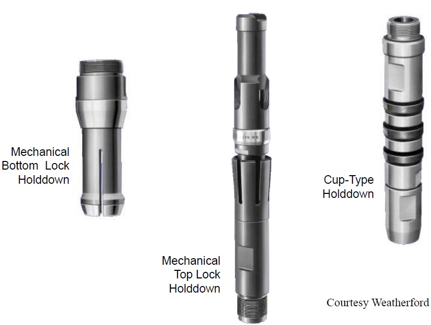
Type of Seating Assembly:
Cup type (C): Economical, but normally cannot be re-seated after workover.
Mechanical (M): Metal seat. More expensive than cup type assembly, but seating mechanism can be used several times.
You May Also Like…
- Why Rod Lift?
- All what you need to know about sucker rod pumping system
- 10 Types of Rod Pumping Units
- Beam Pumping Unit Principles and Components
- Surface Components of Sucker Rod Pumps in different languages
