Major Reference Guides for Well Integrity

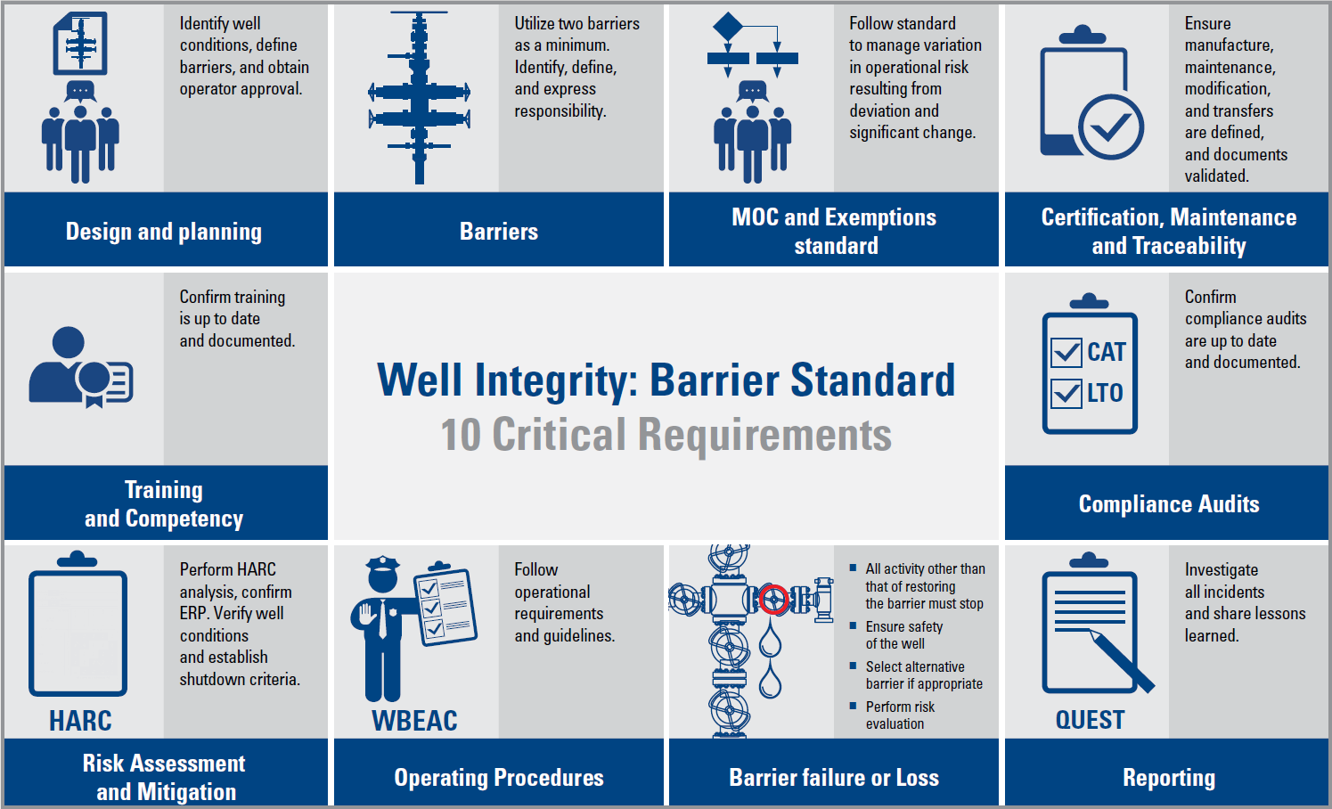
In this article, the major reference guides for Well Integrity are presented. These guides can be considered as reference documents as well as a basis for training classes on the subject of Well Integrity.

The standard defines the minimum functional and performance oriented requirements and guidelines for well design, planning and execution of safe well operations. The focal of the standard is well integrity.

Well integrity is defined to be “application of technical, operational and organizational solutions to reduce risk of uncontrolled release of formation fluids throughout the life cycle of a well”. The standard focuses on establishing well barriers by use of WBE’s (well barrier elements), their acceptance criteria, their use and monitoring of integrity during their life cycle. The standard also covers well integrity management and personnel competence requirements. The standard does not contain any well or rig equipment specifications.”

Continue reading

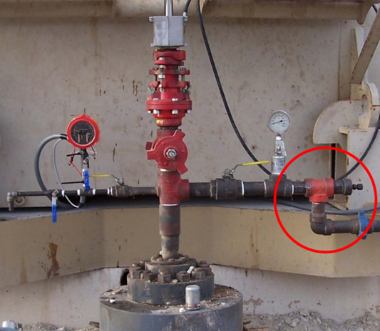
Back Pressure Regulators for Gassy Sucker Rod Lifted Wells

The problem of heading (flow off and pump) is often encountered in gassy wells. This heading effect which can blow the tubing dry occurs as follows:

  • Gas expansion in the tubing as oil from the reservoir travels towards the surface (due to gas pressure decrease).
  • Formation of a gas “plunger” that can push the liquid above it out of the tubing and into the flow line at high speed. As the gas forces the liquids out of the tubing, the pressure in the tubing decreases rapidly and the gas expands even more.
  • This heading behavior of reservoir fluids causes cycles of high production followed by low or no production.

When heading process starts, the expanding gas pushes the liquid into the flowlines and increases production for a short time. In the meantime, the liquid leaving the tubing is replaced by more and more free gas. Eventually, the tubing is blown dry and production stops until the tubing fills with liquid again.

Continue reading

Introduction to Well Integrity

According to Norsok D-010, well integrity is defined as the “application of technical, operational and organizational solutions to reduce the risk of uncontrolled release of formation fluids and well fluids throughout the life cycle of a well”.

Well Integrity is defined in ISO/TS 16530-2 as: “containment and the prevention of the escape of fluids (i.e. liquids or gases) to subterranean formations or surface”

In API RP 65-2, well integrity is defined as: “a quality or condition of a well being structurally sound with competent pressure seals by application of technical, operational, and organizational solutions that reduce the risk of uncontrolled release of formation fluids throughout the well life cycle “.

Following from the aforementioned definitions of well integrity, the personnel planning the drilling and completion of wells will have to identify the solutions that give safe well life cycle designs that meet the minimum requirements of the standard.

Continue reading

Pressure loss calculations through a conduit

Whenever a fluid flows through a conduit pressure loss occurs. Many methods are available to calculate frictional pressure losses. They range from simple empirical equations to rigorous mechanistic multiphase flow models.

Darcy-Weisbach flow equation:

The Darcy-Weisbach flow equation is theoretically sound equation derived from the Conservation of Mass and Conservation of Momentum laws. Named after Henry Darcy and Julius Weisbach, it relates the pressure loss due to friction along a given length of pipe to the average velocity of the fluid flow for an incompressible fluid.

The Darcy-Weisbach equation contains a dimensionless friction factor, known as the Darcy friction factor. This is also variously called the Darcy–Weisbach friction factor, friction factor, resistance coefficient, flow coefficient, or Moody friction factor.

In a cylindrical pipe of uniform hydraulic diameter d, flowing full, the pressure loss due to density and viscous effects dp/dL is proportional to length L and can be characterized by the Darcy–Weisbach equation:

Where:

  • dP/dL = Pressure Gradient (psi/ft)
  • f = friction factor
  • ρ = Fluid density (lb/ft3)
  • v = Fluid velocity (ft/s))
  • d = Hydraulic diameter (ft))

The equation can be written as shown below in both typical US oilfield units and SI units:

Continue reading

Tubing grade guidelines

When selecting steel type for pipes and connections it is important to consider the corrosive environment that the steel will be subjected to. There are several parameters in the well that affect the corrosion, like temperature, chloride ion concentration, partial pressure of CO2 and H2S, pH and presence or absence of Sulphur [Craig et al. 2011].

When selecting a material there are certain aspects that have to be taken into consideration [NORSOK M-001 2004]:

  • Corrosivity;
  • Design life;
  • Availability;
  • Failure possibility and the consequences related to failure;
  • Resistance to brittle fracture;

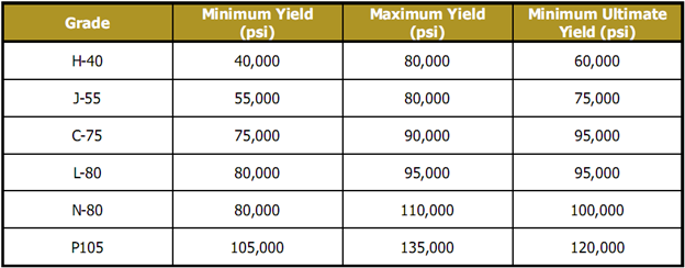
API tubing steel grades are identified by letters and numbers which dictate various characteristics of the steel. For each grade, the number designates the minimum yield strength. Thus L-80 grade steel has a minimum yield strength of 80,000 psi. In other words, it can support a stress of 80,000 psi with an elongation of less than 0.5%. The letter in conjunction with the number designates parameters such as the maximum yield strength and the minimum ultimate strength which for L-80 pipe are 95,000 psi.

The following table shows the yield values for various API tubing grades:

Continue reading