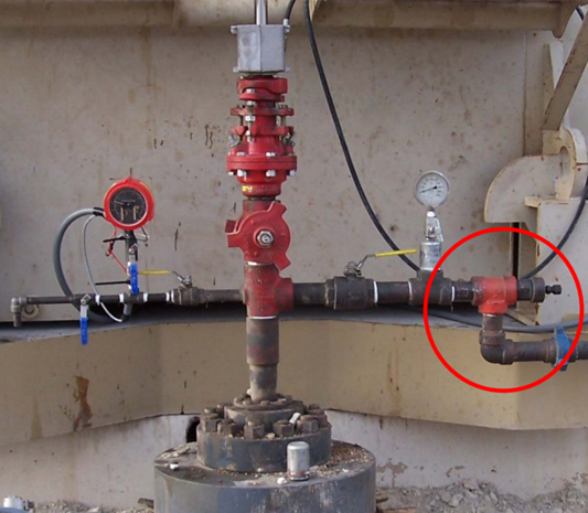
Back Pressure Regulators for Gassy Sucker Rod Lifted Wells

The problem of heading (flow off and pump) is often encountered in gassy wells. This heading effect which can blow the tubing dry occurs as follows:

  • Gas expansion in the tubing as oil from the reservoir travels towards the surface (due to gas pressure decrease).
  • Formation of a gas “plunger” that can push the liquid above it out of the tubing and into the flow line at high speed. As the gas forces the liquids out of the tubing, the pressure in the tubing decreases rapidly and the gas expands even more.
  • This heading behavior of reservoir fluids causes cycles of high production followed by low or no production.

When heading process starts, the expanding gas pushes the liquid into the flowlines and increases production for a short time. In the meantime, the liquid leaving the tubing is replaced by more and more free gas. Eventually, the tubing is blown dry and production stops until the tubing fills with liquid again.

Continue reading

Rod Rotator extends the life of rod-pumped wells

The constant up-and-down movement of a sucker rod creates excessive friction between rods and tubing which can result in premature rod and tubing failures due to excessive wear. If left unchecked, this generally requires a costly intervention to make repairs.

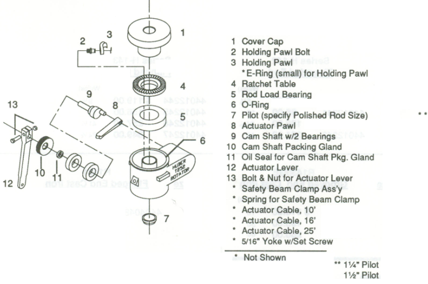
To extend the sucker rod run life, one of the widely used techniques is the use of rod rotators. A rod rotator is a mechanical device installed on the polished rod between the carrier and the polished rod clamp. It incrementally rotates the rod with each stroke. A rotating mechanism with an actuator lever arm is connected to the walking beam with a metal string. As the surface unit moves up and down, it pulls and releases this metal string so that, moves the actuator lever arm up and down. The rotation mechanism is activated and this slowly rotates the polished rod and the rod string below.

Continue reading

Tubing Rotator reduces rod pumping failures

The tubing, in a well produces by the mean of a rod pumping system, represents the second largest investment in the well. Every day, every stroke on the pumping unit can cause wear in the tubing. On ever stroke the rods move up and down. Especially for deviated wells, the rods will always tend to lie on the downside of the tubing. So, on every stroke of the pumping unit, the rods are wearing a path into the metal of the tubing, path that will become a hole in the tubing.

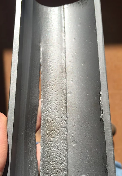
Rod-wear track in tubing (from a 1” Spray-Metal coupling rubbing in 2 7/8” tubing)

Tubing Wear:

In a typical pumping well running at 10 strokes per minute, the rods will move against the tubing 14400 times every day. This wear will eventually cause a tubing failure. A common tubing failure is termed a “tubing split” and normally will be thin on one side of the tubing’s internal surface (about 20% of the tubing’s circumference) and can be detected by pinging with a hammer, cutting open the tubing, or running a thumb inside the tubing to feel for the thin area. The outside of the tubing will normally have a “tubing split” where a thin crack 1 to 5 inches long runs along the longitudinal axis of the tubing as shown in the following figure.

Continue reading

Why Rod Lift?

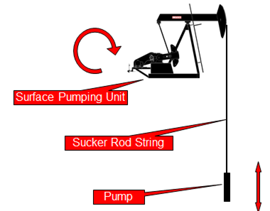
Rod Pumping System is a system of artificial lift using a surface pumping unit to impart reciprocating motion to a string of rods. Rod string then extends to a positive displacement pump placed in well near producing formation. In other words, the primary function of a rod pumping system is to convert the energy supplied at the prime mover into the reciprocating motion of the pumping unit required to transmit energy through the rod pumping to the downhole pump in order to artificially lift the reservoir.

Rod Pumping System:

The rod pumping system is made up of three components:

  • The surface pumping unit: which provides the means of turning the rotating power and motion of the motor into the reciprocating motion at the correct speed needed at the pump.
  • The rod string: that connects the surface unit to the pump and provides the force at the pump to lift the fluid to the surface.
  • The pump: which pumps the fluid to the surface.

The integrity of this pumping system is only as good as each of the links or components.

Continue reading

Torque and Maximum Counterbalance Moment

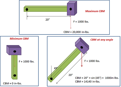
Torque is defined as twisting force. To calculate the torque around the rotation of a crank caused by a weight at the end of the crank, you need to multiply the weight times the horizontal distance from the center of gravity of the weight to point of rotation.

Unit of Torque:

The International System of Units, SI, (the French Système International (d’unités)), suggests using the unit newton meter (N⋅m). The unit newton meter is properly denoted N⋅m or N m. This avoids ambiguity with mN (millinewtons).

In Imperial units, “pound-force-feet” (lbf-ft), “foot-pounds-force”, “inch-pounds-force” are used. Other non-SI units of torque include “meter-kilograms-force” are also used. For all these units, the word “force” is often left out. For example, abbreviating “pound-force-foot” to simply “pound-foot” (in this case, it would be implicit that the “pound” is pound-force and not pound-mass).

Maximum and Minimum Counterbalance Moment:

The crank generates maximum torque when it is in a horizontal position. This maximum torque is known as the Maximum Counterbalance Moment” ( maximum CBM) expressed in inch-pounds.

NB: In rod pumping, the CBM is expressed in thousands of inch pounds.

Continue reading