10 Types of Rod Pumping Units

1. Conventional Unit:

The conventional pumping unit is a modern version of the beam pumping unit first built in 1926 with the invention of crank counterbalance.  It is a rear mounted class 1 lever system with crank counterbalance.

Typically, if one were to drop a plumb line off the equalizer bearing that line would fall over the center of the crankshaft. This machine can be rotated both Clockwise (CW) and Counterclockwise (CCW) with approximately the same performance characteristics.

It is manufactured in a wide variety of sizes and it can be fitted with many types of prime-mover bases that attach to the normal unit base.

This is the most common pumping unit type, because of its relative simplicity of operation, low maintenance requirements and adaptability to a wide range of field applications. As the cranks on a conventional unit rotate, the pitman side members cause the walking beam to pivot on a center bearing, moving the polished rod. Adjustable counterweights are located on the cranks.

As detailed by the article titled “Beam Pumping Unit Principles and Components“, most important parts of the conventional units are: Base, Counterweight, Crank, Samson Post, Horse Head, Walking Beam, Equalizer, Pitman, Gear Reducer, Brake and Prime Mover.

Continue reading

Beam Pumping Unit Principles and Components

Beam pumping Unit Principles:

A beam pumping unit is a machine for translating rotary motion from a crankshaft to a linear reciprocating motion for the purpose of transferring mechanical power to a down-hole pump.

The purpose, simply stated, of the basic system is to transmit energy from the surface to the downhole pump.  The resulting configuration has been referred to as a Sucker Rod Pumping System.

Beam pumping Unit Components: Continue reading

Introduction to AutographPC Sizing and Simulation Software

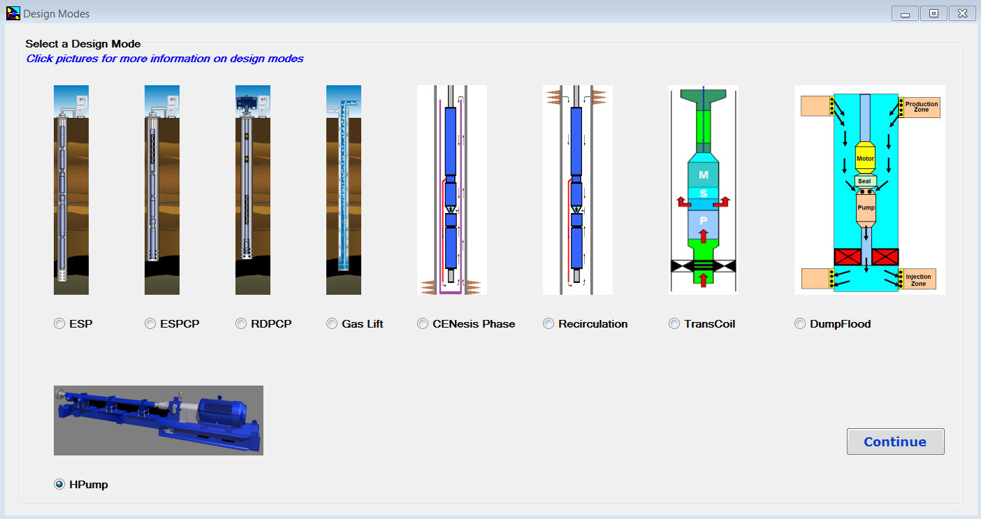
Baker Hughes Centrilift AutographPC ™ is an artificial lift and application simulation software. It’s a powerful tool to give a comprehensive and user-friendly system design. This software can be used to design production systems, including: electrical submersible pumping (ESP) systems; electrical submersible progressing cavity pumping (ESPCP™) systems; rod-driven progressing cavity pumping (RDPCP™) systems; horizontal surface pumping (HPump™) systems; and gas lift systems, etc.

Each system installation is unique and with this software, all the well information, including production characteristics, fluid properties and well conditions, can be entered during the initial design phase to produce the optimum solution for each sizing.

Once installed and launched, Design Modes Screen, shown in the following screenshot, appears. Design Modes screen has been added to AutographPC since July 12, 2017. This is the screen where the user can select a design mode and start a new sizing program.


Continue reading

Drill Stem Test (DST): Qualitative DST Chart

When drilling has reached total depth and the formation to be evaluated has been determined by samples, logs, and cores, a Drill Stem Test may be ordered.

The testing equipment is attached to the end of the drill string. A hydraulic valve system keeps the string dry as it is being lowered into the wellbore. The testing equipment also incorporates a sealing device or packer that effects against the wellbore.

When testing equipment has reached the prospective formation, the formation is isolated from the rest of the wellbore by the packers. A valve opens and the formation is allowed to produce into the dry drill pipe.

At this time, a graphic pressure versus time chart of flow performance is recorded. This chart is produced by mechanical recorders and/or electronic pressure/temperature gauges. The data derived from the Drill Stem Test (DST) give a computation of the formation’s permeability, damage ratio, productivity index, transmissibility and radius of investigation.

After the operator determines that a formation test is to be conducted, the test tool is assembled and lowered into the wellbore. A graphic chart is obtained from two recorders.

Continue reading

What is a Drill Stem Test (DST) and what data is attainable?

Drill stem test (DST) is the conventional method of formation testing and reservoir evaluation which obtains reservoir data under dynamic (rather than static) conditions. A DST is essentially a temporary completion, a method of evaluating reservoir formations without costly and time-consuming completion procedures.

The basic drill stem test tool consists of a packer or packers, valves or ports that may be opened and closed from the surface, and two or more pressure-recording devices. The tool is lowered on the drill string to the zone to be tested.  The packer or packers are set to isolate the zone from the drilling fluid column.

The valves or ports are then opened to allow for formation flow while the recorders chart static pressures.  A sampling chamber traps clean formation fluids at the end of the test.

Analysis of the pressure charts is an important part of formation testing.

Data attainable from a Drill Stem Test

Normal data recovery from a Drill Stem Test includes items such as fluid recovery and description, blow descriptions test times, mud and hole data and the pressure/time data as recovered from the chart record. These items are reported from the field and recorded on a field data sheet or envelope.

In addition to field data (direct information), additional reservoir characteristics may be calculated utilizing the test data recovered in the field (indirect information). Some of these reservoir characteristics are:

Continue reading