Multiphase Flow Properties & Pressure Gradient Calculation

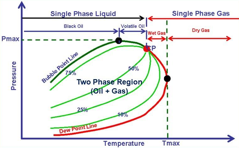
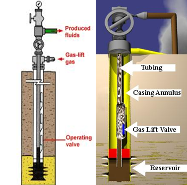
For oil wells, the main component of pressure loss is the gravity or hydrostatic term.  Calculation of the hydrostatic pressure loss requires knowledge of the proportion of the pipe occupied by liquid (holdup) and the densities of the liquid and gas phases.  Accurate modeling of fluid PVT properties is essential to obtain in-situ gas/liquid proportions, phase densities, and viscosities.

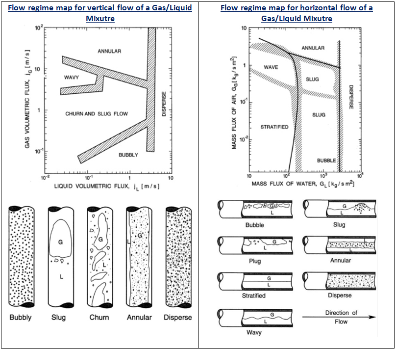
Calculation of holdup is complicated by the phenomenon of gas/liquid slip.  Gas, being less dense than liquid flows with a greater vertical velocity than liquid. The difference in velocity between the gas and liquid is termed the slip velocity.  The effect of slip is to increase the mixture density and hence the gravity pressure gradient.

In the next paragraphs, two-phase flow properties (holdup, densities, velocity, and viscosity) will be detailed. Then the pressure gradient equation which is applicable to any fluid flowing in a pipe inclined at an angle φ is depicted. As well as, the two-phase flow procedure to calculate the outlet pressure is detailed.

Two-Phase Flow Properties:

Holdup:

With reference to multiphase flow in pipes, the fraction of a particular fluid present in an interval of a pipe. In multiphase flow, each fluid moves at a different speed due to different gravitational forces and other factors, with the heavier phase moving slower, or being more held up, than the lighter phase. The holdup of a particular fluid is not the same as the proportion of the total flow rate due to that fluid, also known as its ”cut”. To determine in-situ flow rates, it is necessary to measure the holdup and velocity of each fluid. The sum of the holdups of the fluids present is unity.

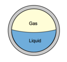
1- Liquid and Gas Holdup (HL & Hg):

HL is defined as the ratio of the volume of a pipe segment occupied by the liquid to the volume of the pipe segment. The remainder of the pipe segment is of course occupied by gas, which is referred to as Hg.

Hg = 1 – HL

Continue reading

Multiphase flow regimes

Flow Regime maps are useful tools for getting an overview over which flow regimes we can expect for a particular set of input data. Each map is not, however, general enough to be valid for other data sets. It gives a description of the geometrical distribution of a multiphase fluid moving through a pipe. Different flow regimes are used to describe this distribution, the distinction between each one being qualitative and somewhat arbitrary. In vertical or moderately deviated pipes, the most common flow regimes for gas-liquid mixtures are bubble flowslug flowmist flow, churn flow and annular flow. In horizontal wells, there may be stratified or wavy stratified flow in addition to many of the regimes observed in vertical wells. Two-phase flow regimes have often been presented as plots, or maps, with the phase velocities or functions of them on each axis. Earlier maps were named after their authors, for example Griffith-Wallis, Duns-Ros and Taitel-Dukler. The following Figures give an example of flow regime map for a vertical and horizontal flow of a Gas/Liquid mixture.

Continue reading

Hydrocarbon Phase Behavior

To understand the complex behavior of a reservoir fluid ” Hydrocarbon Phase Behavior “, let’s, first of all, consider the simple case of a single-compound hydrocarbon, ethane for example, initially in gas form in a cell containing mercury. As mercury is gradually injected, the gas is subjected to a continuously increasing pressure. The temperature is held constant. Actually, isothermal conditions simulate a reservoir’s generally constant temperature. At some unique pressure – the vapour pressure – the gas will condensate into a liquid.

Vapour Pressure line: is the line defining the pressures at which the transition from gas to liquid occurs. Above this line, the single-compound hydrocarbon exists as a liquid, below as gas.

Critical Point: is the point at which it is no longer possible to distinguish whether the fluid is liquid or gas. The intensive properties of both phases are identical.

Naturally occurring hydrocarbons are more complex than the system shown above. They contain much more members of paraffin series and usually some non-hydrocarbon impurities. Nevertheless, a phase diagram can similarly be defined for complex mixtures. A typical diagram for a natural gas is shown in the following graph:

Continue reading

“Rocking” Gas-Lift Wells


The operation of ”rocking” a gas-lift well, also called: ”fluid level depressing”, is required to unload the well when the fluid column is heavier than the available lift pressure. Thus, the top gas lift valve cannot be uncovered with the available injection-gas pressure.

”Rocking” the well consists on applying an injection gas pressure simultaneously to the tubing and casing. The injected gas in the tubing will push the fluid column back into the formation; therefore reduce height, thus the weight of the fluids being lifted and allow unloading with the available lift pressure.

The tubing pressure is released rapidly, and the source of the major portion of the fluid entering the tubing is load fluid from the annulus. This procedure may be required several times to lower the fluid level in the casing annulus below the depth of the top gas lift valve.

PS: Several hours may be required to ”rock” a well having low reservoir permeability.

”Rocking” Procedure:

Continue reading

Gas Lift Instability

By Burney Waring, Consultant at WaringWorld, Inc.

Someone asked me recently about gas lift well instability. This is how I learned to determine if gas lift will be unstable, that is deciding if the well will exhibit casing heading.

As far as I know, this was invented by Dick ter Avest with Shell in 1995, but I think Wim der Kinderen was finally able to explain it to me so I could understand it.

Continue reading