By Marcelo Hirschfeldt, Instructor y Consultor en áreas de Tecnologías de Producción y Gerenciamiento de Activos Petroleros
Tag Archives: artificial lift
Fundamental principles of physics used in artificial lift design
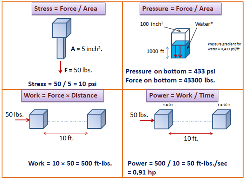
In the present article, we discuss a couple of physical quantities used in artificial lift design such as the concept of stress, pressure, work, power, energy, machine, and efficiency.

Stress is defined as force divided by area. So that, to reduce the stress you can either reduce the force or increase the cross sectional area it acts on.
Stress = Force / Area
ESP design – Step 3: Gas Calculations
The presence of free gas in the tubing above the pump changes the fluid density, consequently reduces the required discharge pressure. Also the performance of centrifugal pumps is considerably affected by the presence of free gas in the pumped fluid. The pump starts producing lower than normal head as the produced GLR (Gas to Liquid Ratio) at the pumping conditions increases beyond a critical value. The critical value of the ratio or percentage of free gas present at the pump intake to the total volume of fluid depends on the pump impeller design (typical critical values are shown in the article “ESP: Gas handling device “). Therefore, it is essential to determine the percentage of free gas by volume at the pumping conditions in order select the proper pump and gas handling device (if required).
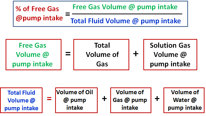
Percentage of free gas by volume:
Assuming that Solution GOR (Rs), Gas Volume Factor (Bg) and Oil Formation Volume Factor (Bo) are known, the total volume of fluids and the percentage of free gas released at the pump intake should be calculated.

ESP design – Step 1: Basic data
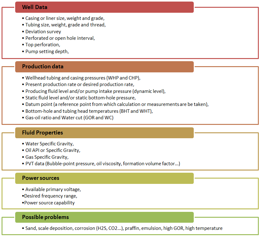
As described in the previous article ESP nine step design procedure, Centrilift has established a nine-step procedure to design the appropriate electrical submersible pump. The first step of this ESP design procedure, and certainly the most important step, consists on collecting the basic data. This is the most important step because all the others design steps will depend on the basic data selected in step 1. If the basic data quality is good the design will be good and the ESP will operate at its optimum conditions. Otherwise, if the input data quality is poor the design will usually be marginal.
A list of required data is outlined next:

Introduction to transformer: How it works?
The transformer is used to convert the incoming voltage at the location to the correct voltage (for the submersible motor in case of ESP). Transformer selection is based on mainly 4 parameters:
- Power rating in KVA (Kilo Volt Amperes),
- Primary voltage,
- Secondary voltage,
- Tap arrangement.
Power rating in KVA for three phase transformer:
The calculation of power rating in KVA for a Three Phase Transformer is based on Winding Voltage and Amperage information. The simple formula to calculate the rating of three phase transformers is:
KVA = (√3. V x I) /1000
Refer to the post titled “How to Calculate the Required KVA Rating for three Phase Transformers? ” for more details.


