Pump Shaft

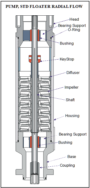
The pump shaft is coupled to the motor shaft through the intake and seal shafts. It transmits the rotary motion from the motor to the impellers of the pump stage. Care must be taken when selecting the shaft material for each application. There are two main considerations: Shaft Strength and Well Fluid Composition.

The diameter of the shaft is minimized as much as possible because of the restrictions placed on the pump outside diameter. The pump power requirements determine if a normal, high-strength, or ultra-high-strength shaft is needed. Most manufacturer’s catalog information specifies what each shaft can handle.

The well fluid composition determines what metallurgy should be used (depends on corrosion protection required).

Shaft Bushings and Shaft Stabilizer Bearing:

Operating a pump outside the manufacturers recommended operating range for extended periods of time will cause excessive wear on the pump stages due to down thrust or up thrust. Thrust wear causes the shaft to vibrate and transfer adverse vibration pulses to other system components, such as the motor protector where eventual fluid entry into the motor may result in a motor burnout.

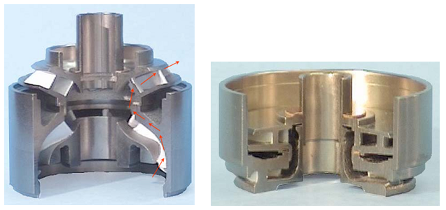
To stabilize and support the shaft, most pumps contain two shaft bushings; one at the top and one at the bottom of the pump housing. Pump shafts may be up to 30-feet in length supported with one or two shaft bearings, depending on the manufacturer. The hub and wear rings on the impeller function as journal bearings against the diffuser. Because journal bearings are made from Ni-resist they tend to be very soft and susceptible to abrasion wear. To mitigate radial wear problems shaft stabilizer bearings can be used.

Continue reading

Centrifugal Pump ( ESP Pump)

Pump Theory:

The term “centrifugal pump” has been used to describe a wide variety of pumping applications and designs throughout the years. A Centrifugal Pump is a machine that moves fluid by spinning it with a rotating impeller in a diffuser that has a central inlet and a tangential outlet.  The path of the fluid is an increasing spiral from the inlet at the center to the outlet tangent to the diffuser. The fluid rotational motion is the result of the concept of centrifugal forces.

The pressure (head) develops against the inside wall of the diffuser because of the curved wall forces fluid to move in a circular path.

Continue reading

Submersible Pump System Overview

The submersible pump system consists of both downhole and surface components. The main surface components are transformers, motor controllers, junction box and wellhead. The main downhole components are the motor, seal, pump and cable. Additional downhole components may be included to the system: data acquisition instrumentation, motor lead extension, cable bands and protectors, gas separator, check and drain valves.

The following video gives a quick equipment overview of the ESP submersible pumping system:


The following figure shows schematic diagram of a submersible pump installation:

Continue reading

Step-by-step petrophysical interpretation in a carbonates field to understand high water production

I like to believe that depending on the specific needs and goals, each reservoir needs a customized characterization workflow. In the case presented in this post, the goal was to understand the reasons behind the high water production in 3 recent drilled wells:

  • Well 1: Decent initial hydrocarbons production followed by lots of water.
  • Well 2: Lots of water.
  • Well 3: Low rate – mainly water, some hydrocarbons.

In order to accomplish the goal, a step-by-step petrophysical characterization is presented including the following aspects: Lithology, Porosity, Water saturation, Permeability, Fractures and secondary porosity, and capillary pressure.

There are other aspects from different disciplines that could be integrated to this post, but I wanted to keep the emphasis on applied petrophysics.

Actions taken as a consequence of the findings described in this post added significant economic value to the project.

Continue reading

How To Easily Read A Well Log in 5 Minutes Using ‘Six Ko Ko​ Rules’

How To Easily Read A Well Log in 5 Minutes Using ‘Six Ko Ko Rules’

By Dosh Nazlan, Petrophysicist.

Petrophysicists look at the well log patterns, recognize the trends, and then turn those patterns into reservoir knowledge.

Well logs can tell us many stories about our reservoir. Each colorful line, each curve deflection and each curve type create the story of our reservoir.

Each reservoir story is different from one another.

But for sure, every story begins the same way. The story starts when the oil and gas, trapped inside the reservoir for million of years, get very excited to come out.

Our main task is to figure out the right story by using well logs and other lab data to make the storyline better.

When we run well logs, these hydrocarbon pools tell us everything – where they are, how they look like and how much they are, so we know how to get them.

But before we understand any story, we need to be able to read these well logs.

My first mentor, Ko Ko Kyi, first taught me how to read and interpret well logs just by looking at the well log patterns. I want to share the same tips with you today.

It’s just a common sense, step-by-step approach in interpreting any well logs. But the results are magical.This is a technique I called ‘The Ko Ko Rules’.

Continue reading