Variable Frequency Drive Basics

In this article, Variable Frequency Drive (also, named: Variable Speed Drive) basics are presented in a simple and easy way with explanation graphs. To understand how the Frequency Speed Controller operates, it is necessary to understand how the VSD supplies variable voltage and frequency for speed control.

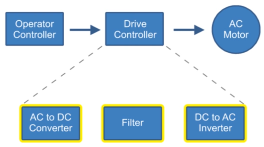
The below block diagram illustration depicts a typical three-phase AC variable speed drive system. It has three main components: an Operator Control, a Drive Controller, and an AC Motor.

An Operator Control device provides a means to start and stop the motor and adjust the operating speed. The Drive Controller consists of a variety of components that work together to convert an AC input into a frequency and voltage output necessary to change the speed of an AC motor.

Main sections of a Variable Frequency Drive:

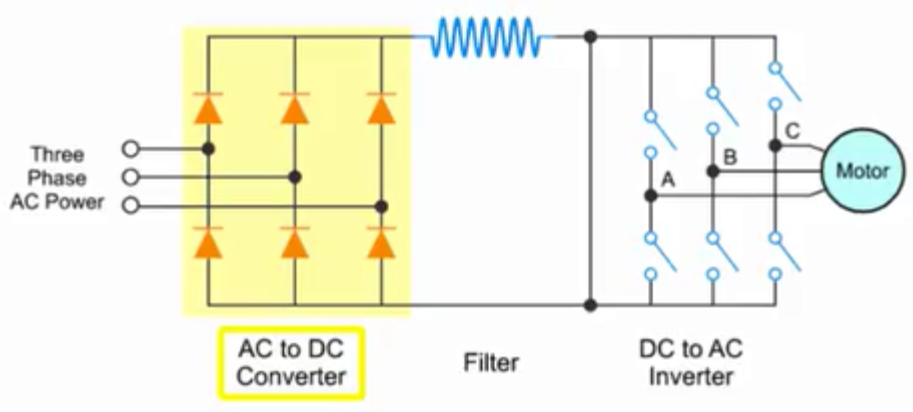
The converter section:

This section converts the incoming 3-phase AC voltage to DC voltage. The converter is essentially a 3-phase, full wave rectifier with Silicon Control Rectifiers, a specialized type of control diode, in the bridge.

The following video explains what SCR is and how it works:

Continue reading

Introduction to transformer: How it works?

The transformer is used to convert the incoming voltage at the location to the correct voltage (for the submersible motor in case of ESP). Transformer selection is based on mainly 4 parameters:

  • Power rating in KVA (Kilo Volt Amperes),
  • Primary voltage,
  • Secondary voltage,
  • Tap arrangement.

Power rating in KVA for three phase transformer:

The calculation of power rating in KVA for a Three Phase Transformer is based on Winding Voltage and Amperage information. The simple formula to calculate the rating of three phase transformers is:

KVA = (√3. V x I) /1000

Refer to the post titled “How to Calculate the Required KVA Rating for three Phase Transformers? ” for more details.

Continue reading

Cable Armor

As per API RP11S5, cable armor is the outer covering of the cable which provides mechanical protection during installation and removal of cables. In addition to mechanical protection, the armor provides mechanical constraint against swelling and expansion of underlying elastomeric materials in case of any exposure to well fluids.

Continue reading

Braids and Coverings

As per API RP11 S5, supplementary layers of materials, named: braids and coverings, are used to guarantee a specific mechanical performance characteristics. It could be either applied over the insulation or on both sides of the jacket. Braids and coverings provide additional strength and protect the underlying cable components. On the other hand, these materials increase the cable diameter and the associated cost. Furthermore, they are also susceptible to deterioration depending on well fluids and conditions.

Continue reading

Cable Jackets

As per API RP11S5, cable jackets are protective coverings used to mechanically shield the insulation from the downhole environment. The jacket materials protect the insulation from mechanical abuse associated with handling. Some jacketing material may provide secondary insulation. The most used types of jackets in submersible pump cable are made of: EPDM elastomers or nitrile.

Continue reading