ESP Accessory Equipment

Junction box, Check and Drain Valves, Downhole Sensor and Centralizers are some kinds of  ESP Accessory Equipment. These type of equipment could play an important role to operate the ESP efficiently and maximize it run lifetime.

Junction Box:

The power cable coming from the well is connected to a surface electric cable leading to the switchboard. As seen in the figure below, the two cables are joined in the junction box, also called a “vent box”. The surface cable connects the junction box to the motor control panel and the motor control panel to the secondary side of the transformers.
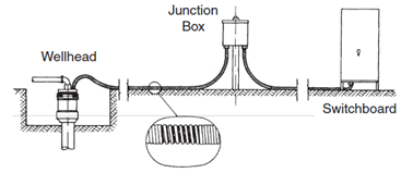
It is a ventilated, weatherproof box performing the following three important functions:

  • Provides the electrical connection between the downhole and the surface electric cable.
  • Vents any gas to the atmosphere which might reach this point due to migration of well gases up the ESP power cable. The venting of gas eliminates the danger of fire or explosion that could happen if gases travel in the cable to the switchboard.
  • Acts as an easily accessible test point for electric checks of the downhole equipment.

Continue reading

Wellhead Equipment for ESP

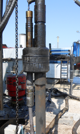
Wellhead Equipment for ESP provides a tubing support and allows the power cable to pass from the surface into the well bore. The wellhead is equipped with a wellhead feed through mandrel or pack-off method. It provides a positive seal around the cable. Wellheads and cable pack-offs are available in various pressure ratings and hanging load capacities.

Wellhead Feedthrough, Penetrator, lower and upper pigtails:

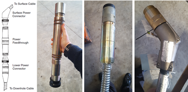
The electrical connection of surface and downhole power cables is detailed in figures below. The tubing hanger holds a feed-through mandrel (also called: well penetrator) equipped with the proper seals. Feed-through mandrel seals contain well pressure and prevent gas leaks at the surface. Power cables are connected to the two ends of this device via their three-phase connectors (also called: lower and upper pigtails).


Continue reading

ESP motor Switchboard

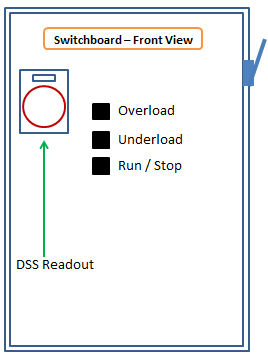
The motor switchboard, as shown in Figure below, provides the means for turning the pump motor on and off, and provides electrical protection for the motor and cable.

If we start at the line side of a switchboard and move through to the load side, we will find something similar to the Switchboard shown in the figure below.

Manual disconnect (switch):

This switch is used to disconnect the controller from the main power supply after the motor has been stopped.

Continue reading

ESP Power Cable Accessories

ESP Power Cable Accessories, namely: Cable Bands and Cable Guards, are used to protect and support ESP cable, control lines and injection lines. There are used also to protect the power cable from damage during installation, operation and pulling. In this article, the roles and specifications of these accessory equipment’s are detailed, as well as recommended practices related to their use and selection.

Cable Bands:

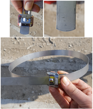
Cable bands are used to attach the cable to the tubing during installation. Bands are provided using three different materials. Black Steel Bands are used in wells with corrosive problems. Stainless Steel Bands are used in moderately corrosive well (with no H2S present in the well). And Monel Bands are used in corrosive environments.

Most cable bands are 3/4 in. (19 mm) wide and approximately .025 in. (0.6 mm) thick.

Cable bands can be installed by using hand-banding tools or by using power-banding tools. The advantage of power banding tools is the bands are attached with the same tension.

The following video shows how to install Cable bands using Power-Banding Tool:

Recommended practices related to cable bands and their use:

Continue reading

Motor Lead Extension

The Motor Lead Extension is a “special power cable extending from the pothead on the motor to above the end of the pump where it connects with the power cable (API RP 11S4).

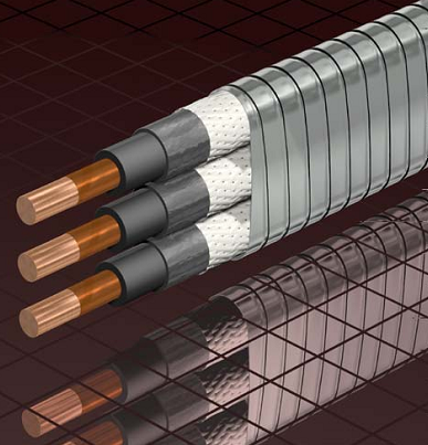
A low-profile cable (flat configuration) is usually needed in this area due to limited clearance between the pump housing and the well casing”.

It is recommended to select a length at least 6 ft. (1.8 m) longer than the upper end of the pump. The length of MLE has to be select in a way to avoid a splice over a tubing collar. Doing so could allow the cable to catch on the wellbore casing and damage the equipment.

The motor lead extension operates under extremely adverse conditions. This is due to the restricted size, the high mechanical stresses, and the high temperatures involved. Because of these effects, motor lead extensions are usually replaced every time a cable is reused.

Continue reading