Power losses in cables

Cable power losses or power drop are due to the conductor resistance heating that occurs when current flows. These cable losses are more often called KW losses or I²R losses. This is expressed by the following formula:

Power losses = 3 × (I²R) /1000

Where: Power losses in kW units, I is the current (in amps) and R (in ohms) is the average conductor resistance.

How to lower the resistance in the cable?

Power lost in a cable depends on the cable length, cable size and the current through the cable. Therefore, there are three ways to lower the resistance in the cable:

  • Shorten the length of the cable,
  • Increase the size of the conductor,
  • Decrease the current through the cable.

Continue reading

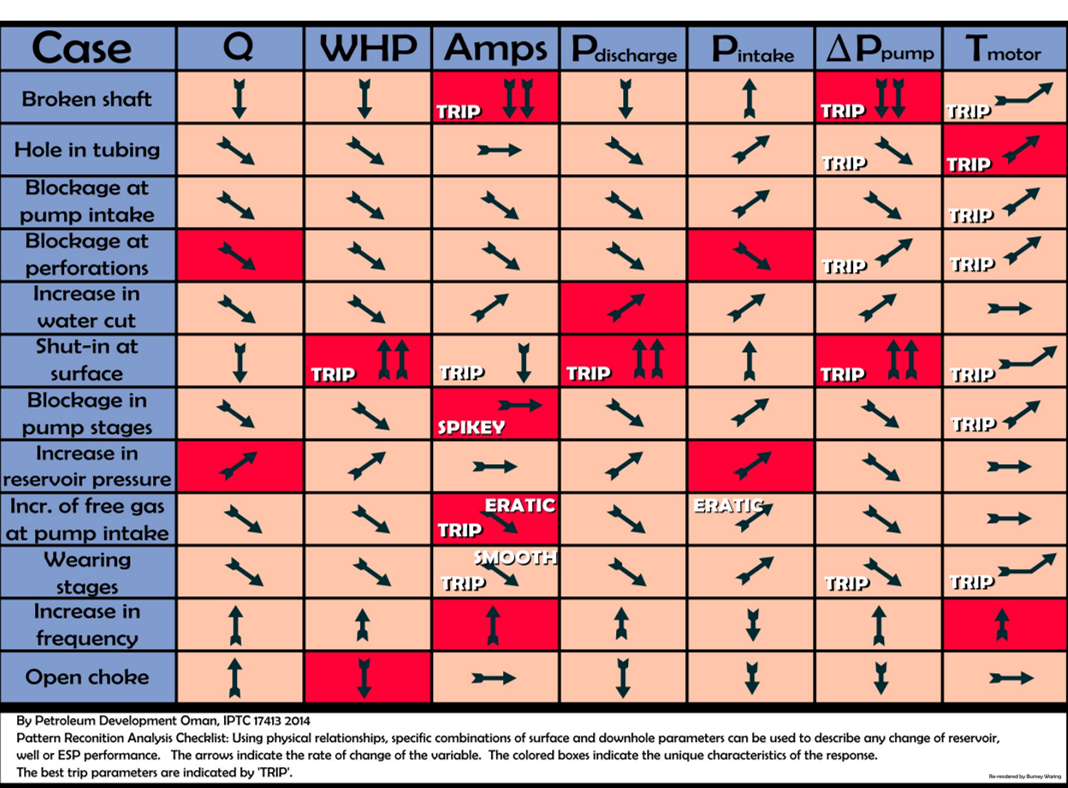
ESP Diagnostic Diagram


ESP Diagnostic Diagram

By Burney Waring, Consultant at WaringWorld, Inc.

One of my clients brought this diagram to my attention recently. The paper, by Petroleum Development Oman and Engineering Insight Ltd of Aberdeen, was very useful and included an especially useful diagram, but the diagram was not so easy to read or print in a larger size. I tried to improve the image so that it would be even more helpful. All credit goes to the authors and their paper IPTC 17413 2014, available on SPE’s OnePetro.

Here is the full size diagram:

Continue reading

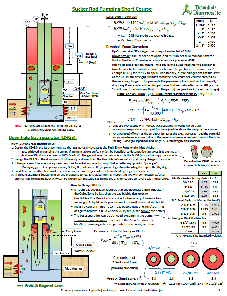
All what you need to know about sucker rod pumping system

All what you need to know about sucker rod pumping system:

This article will give you a summary of all what you need to know about sucker rod pumping system:

  • Calculate the expected production rate,
  • Understand downhole pump operation,
  • Understand the concept of Fluid Load (Fo) and Pump Intake & Discharge Pressures (PIP/PDP),
  • How to avoid Gas Interference and how to design a downhole gas separator?
  • The concept of dynamometer cards and how to interpret pump card shapes?
  • Understand the causes of incomplete pump fillage,
  • SRP equipment – design considerations,
  • SRP Optimization (during design phase, while pulling the well and during operations & monitoring),
  • Fluid level & Dyno surveys,
  • Concepts of Gas interference (or “Gas Pound”) & Fluid Pound,
  • Rod, Tubing and Casing Specifications,
  • API Nomenclature of Pumping Unit and Pump.

Continue reading

ESP Motor Shroud: Applications, Configurations and Selection Criteria

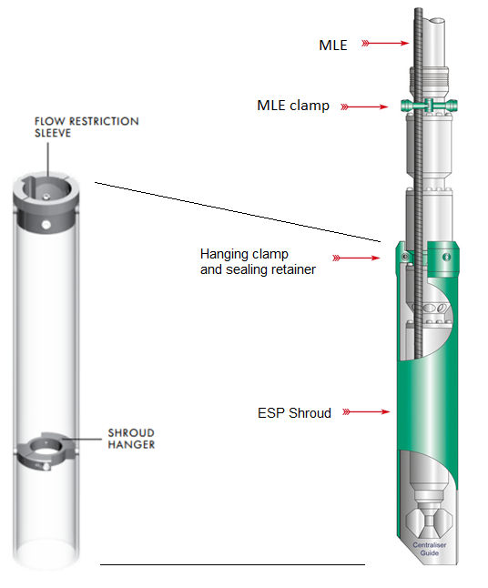
The ESP motor Shroud is a cylinder fitted around the Motor, Protector and Intake sections of an ESP. It is designed to provide cooling to the motor when fluid velocities are below minimum by reducing the annular area between the ESP and the casing bore.

The Shroud is simply constructed with a length of tube long enough to swallow the Motor, Protector and Intake sections, and is bolted with a split clamp unit to first ESP neck located above Intake. The MLE cable is run through the shroud. The shroud assembly is made up of a jacket (a length of casing or pipe), a hanging clamp and sealing retainer for the top, and a centralizer for the bottom.

Above the Shroud, an MLE Clamp is normally fitted to secure the MLE to the Discharge Head. At the bottom end, a Centralizer Guide is fitted to help secure the ESP section within the Shroud. The Shroud can be manufactured from a thin casing, stainless steel or fiberglass.

Continue reading