As the name suggests “ Pump Intake ” is where the well fluid enters the Submersible Pumping System. Care should be taken when designing a submersible pump intake because it is such a vital point in the system that when not designed properly may create all kinds of problems.
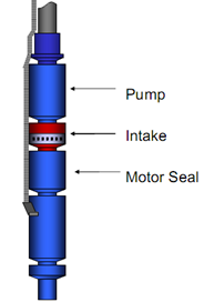
There are three types of intake Sections:
- Standard Intakes or BOI (bolt on intake),
- Integral (manufactured as part of the pump),
- Gas Separators (static and rotary gas separators).
Standard and Integral Intakes:
Standard intakes (BOI and integral) do not separate gas. Some gas separation might occur, but it will only be natural separation due to some of the gas not turning and going into the intake when the rest of the fluid does. Therefore, the standard intake is for wells that produce with a very low free gas to liquid ratio. The amount of free gas by volume at pump intake conditions should be no more than 10% to 15% by volume (depends if it is a radial or mixed flow stage)
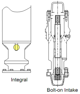
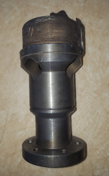
Usually, the pump intake is a separate component that bolts onto the bottom of the pump section. Occasionally, the pump is built in either a lower tandem or single configuration. In these cases, the pump intake as an integral part of the pump assembly.
Gas Separators:
Gas Production has been a “problem” since the early days of oil production. It limited production on many oil wells producing with pumps.
A gas separator is still an intake, but with some special features designed to keep free gas from entering the pump.
There are two types of gas separators being utilized by the industry at this time. They are “static (reverse flow) gas separator” and “dynamic (rotary) gas separator”.
1. Static Gas Separators (also named: Reverse Flow Gas Separator):
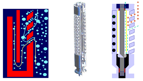
Original gas separator designs were based on increasing gas separation by forcing the fluid flow to reverse in the well-bore. This is where the name of this type of gas separator, Reverse Flow, comes from. Since this type of gas separator does no real “work” on the fluid, it is also called a “static” gas separator.
As well fluid enters the gas separator it is forced to change direction. Some of the gas bubbles continue to rise instead of turn or rise inside of the gas separator, exit the housing and continue to rise.
Reverse flow gas separators are highly dependent on annular area, fluid velocity, and relative specific gravity of the gas and liquid. It usually separates up to 20% (by volume) free gas.
PS: Reverse flow gas separation can also be accomplished by a shroud unit in wells of sufficient diameter by setting the pump below the well perforations with proper motor cooling.
2. Dynamic Gas Separator:
Dynamic is defined in the dictionary as “Force Producing Motion”, which implies that this type of gas separator uses force.
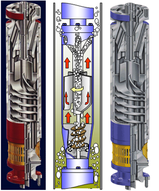 |
The rotary separator separates free gas with an efficiency of 75% to 90% under most conditions. It should be used where the free gas available at the intake exceeds 20% unless there is abrasive material in the fluid.
The rotary gas separator design works in a similar fashion to a centrifuge. It utilizes a specially designed rotating chamber (rotor), paddle wheel, or induced vortex to impart centrifugal force on the fluid. The rotor or induced vortex forces the heavier fluid to the outside & allows the free gas to migrate to the center of the chamber and exits through the discharge ports back into the well. Gas separator assemblies are often connected in tandem to improve the overall efficiency in high gas applications.
|
NB: Do not design or operate a gas separator under a packer or where the casing is not vented.
Even though gas separators are very efficient in relatively high GLR wells, they have some known limitations include:
- They are not effective under slugging conditions,
- Not good with emulsions,
- May fail due to vibration effects at very high gas to liquid ratios,
- Solids can cause catastrophic failure of separator internals.
NB: For more information related to gas separators, read SPE papers: ” Effect of Gaseous Fluids on Submersible Pump Performance ” and ” Gas Separator Performance for Submersible Pump Operation “


