Introduction to AutographPC Sizing and Simulation Software

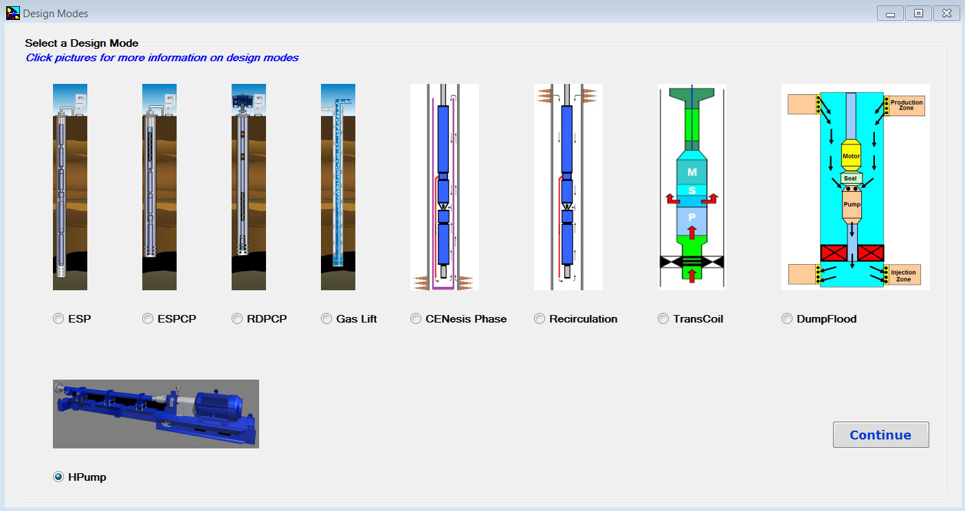
Baker Hughes Centrilift AutographPC ™ is an artificial lift and application simulation software. It’s a powerful tool to give a comprehensive and user-friendly system design. This software can be used to design production systems, including: electrical submersible pumping (ESP) systems; electrical submersible progressing cavity pumping (ESPCP™) systems; rod-driven progressing cavity pumping (RDPCP™) systems; horizontal surface pumping (HPump™) systems; and gas lift systems, etc.

Each system installation is unique and with this software, all the well information, including production characteristics, fluid properties and well conditions, can be entered during the initial design phase to produce the optimum solution for each sizing.

Once installed and launched, Design Modes Screen, shown in the following screenshot, appears. Design Modes screen has been added to AutographPC since July 12, 2017. This is the screen where the user can select a design mode and start a new sizing program.


Continue reading

Y-tool system – A solution to enable well access below ESP

The Y-tool is a solution to enable production-logging and well intervention below a working ESP at any point in time during production without pulling the completion string. The Y-tool is installed on the production tubing, providing two separate conduits. One conduit concentric with the production tubing and enables access to the reservoir below the ESP. The second conduit is offset and used to support the ESP system. Flow rates in different perforation intervals and other valuable geophysical information could be collected for production optimization and enhanced recovery plans.

With an ESP Y-tool in place, Operators are able to carry out wireline or coiled tubing logging, memory gauge deployment, tubing-conveyed perforation, well treatment and stimulation operations, effectively managing production operations and reservoir performance without pulling the ESP, dual ESP installation and bridge plug setting for water shutoff, etc.

Wireline or coiled tubing plugs can be used to seat in a nipple profile in the Y-tool to enable intervention or logging operation without retrieval of the completion. If required, the ESP can be run with these plugs in place to perform production logging or other well interventions.


Continue reading

ESP Power Cable Accessories

ESP Power Cable Accessories, namely: Cable Bands and Cable Guards, are used to protect and support ESP cable, control lines and injection lines. There are used also to protect the power cable from damage during installation, operation and pulling. In this article, the roles and specifications of these accessory equipment’s are detailed, as well as recommended practices related to their use and selection.

Cable Bands:

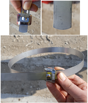
Cable bands are used to attach the cable to the tubing during installation. Bands are provided using three different materials. Black Steel Bands are used in wells with corrosive problems. Stainless Steel Bands are used in moderately corrosive well (with no H2S present in the well). And Monel Bands are used in corrosive environments.

Most cable bands are 3/4 in. (19 mm) wide and approximately .025 in. (0.6 mm) thick.

Cable bands can be installed by using hand-banding tools or by using power-banding tools. The advantage of power banding tools is the bands are attached with the same tension.

The following video shows how to install Cable bands using Power-Banding Tool:

Recommended practices related to cable bands and their use:

Continue reading

ESP Motor Shroud: Applications, Configurations and Selection Criteria

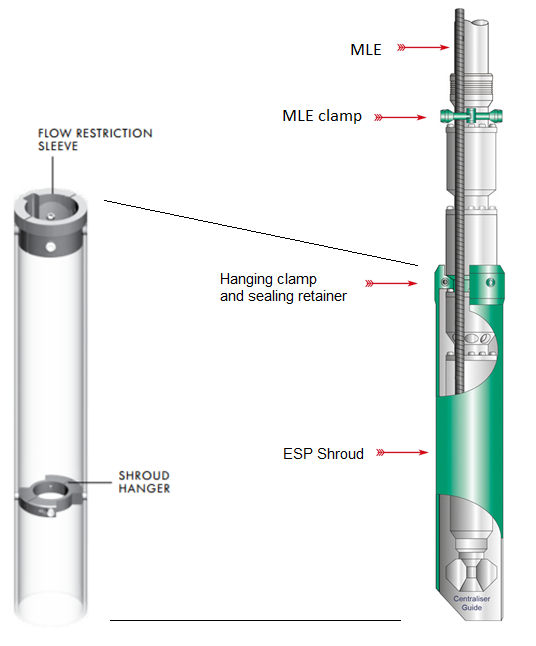
The ESP motor Shroud is a cylinder fitted around the Motor, Protector and Intake sections of an ESP. It is designed to provide cooling to the motor when fluid velocities are below minimum by reducing the annular area between the ESP and the casing bore.

The Shroud is simply constructed with a length of tube long enough to swallow the Motor, Protector and Intake sections, and is bolted with a split clamp unit to first ESP neck located above Intake. The MLE cable is run through the shroud. The shroud assembly is made up of a jacket (a length of casing or pipe), a hanging clamp and sealing retainer for the top, and a centralizer for the bottom.

Above the Shroud, an MLE Clamp is normally fitted to secure the MLE to the Discharge Head. At the bottom end, a Centralizer Guide is fitted to help secure the ESP section within the Shroud. The Shroud can be manufactured from a thin casing, stainless steel or fiberglass.

Continue reading

Pump Shaft

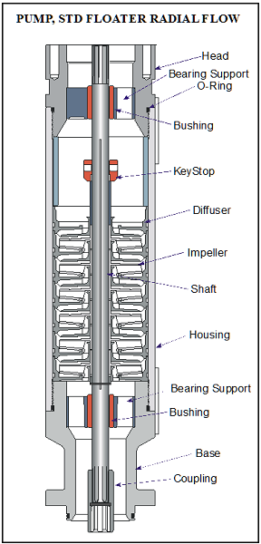
The pump shaft is coupled to the motor shaft through the intake and seal shafts. It transmits the rotary motion from the motor to the impellers of the pump stage. Care must be taken when selecting the shaft material for each application. There are two main considerations: Shaft Strength and Well Fluid Composition.

The diameter of the shaft is minimized as much as possible because of the restrictions placed on the pump outside diameter. The pump power requirements determine if a normal, high-strength, or ultra-high-strength shaft is needed. Most manufacturer’s catalog information specifies what each shaft can handle.

The well fluid composition determines what metallurgy should be used (depends on corrosion protection required).

Shaft Bushings and Shaft Stabilizer Bearing:

Operating a pump outside the manufacturers recommended operating range for extended periods of time will cause excessive wear on the pump stages due to down thrust or up thrust. Thrust wear causes the shaft to vibrate and transfer adverse vibration pulses to other system components, such as the motor protector where eventual fluid entry into the motor may result in a motor burnout.

To stabilize and support the shaft, most pumps contain two shaft bushings; one at the top and one at the bottom of the pump housing. Pump shafts may be up to 30-feet in length supported with one or two shaft bearings, depending on the manufacturer. The hub and wear rings on the impeller function as journal bearings against the diffuser. Because journal bearings are made from Ni-resist they tend to be very soft and susceptible to abrasion wear. To mitigate radial wear problems shaft stabilizer bearings can be used.

Continue reading