ESP Motor Shroud: Applications, Configurations and Selection Criteria

The ESP motor Shroud is a cylinder fitted around the Motor, Protector and Intake sections of an ESP. It is designed to provide cooling to the motor when fluid velocities are below minimum by reducing the annular area between the ESP and the casing bore.

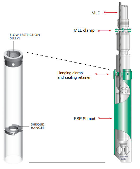
The Shroud is simply constructed with a length of tube long enough to swallow the Motor, Protector and Intake sections, and is bolted with a split clamp unit to first ESP neck located above Intake. The MLE cable is run through the shroud. The shroud assembly is made up of a jacket (a length of casing or pipe), a hanging clamp and sealing retainer for the top, and a centralizer for the bottom.

Above the Shroud, an MLE Clamp is normally fitted to secure the MLE to the Discharge Head. At the bottom end, a Centralizer Guide is fitted to help secure the ESP section within the Shroud. The Shroud can be manufactured from a thin casing, stainless steel or fiberglass.
Continue reading

Pump Shaft

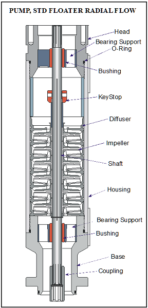
The pump shaft is coupled to the motor shaft through the intake and seal shafts. It transmits the rotary motion from the motor to the impellers of the pump stage. Care must be taken when selecting the shaft material for each application. There are two main considerations: Shaft Strength and Well Fluid Composition.

The diameter of the shaft is minimized as much as possible because of the restrictions placed on the pump outside diameter. The pump power requirements determine if a normal, high-strength, or ultra-high-strength shaft is needed. Most manufacturer’s catalog information specifies what each shaft can handle.

The well fluid composition determines what metallurgy should be used (depends on corrosion protection required).

Shaft Bushings and Shaft Stabilizer Bearing:

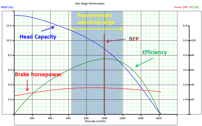
Operating a pump outside the manufacturers recommended operating range for extended periods of time will cause excessive wear on the pump stages due to down thrust or up thrust. Thrust wear causes the shaft to vibrate and transfer adverse vibration pulses to other system components, such as the motor protector where eventual fluid entry into the motor may result in a motor burnout.

To stabilize and support the shaft, most pumps contain two shaft bushings; one at the top and one at the bottom of the pump housing. Pump shafts may be up to 30-feet in length supported with one or two shaft bearings, depending on the manufacturer. The hub and wear rings on the impeller function as journal bearings against the diffuser. Because journal bearings are made from Ni-resist they tend to be very soft and susceptible to abrasion wear. To mitigate radial wear problems shaft stabilizer bearings can be used.

Continue reading

Submersible Pump System Overview

The submersible pump system consists of both downhole and surface components. The main surface components are transformers, motor controllers, junction box and wellhead. The main downhole components are the motor, seal, pump and cable. Additional downhole components may be included to the system: data acquisition instrumentation, motor lead extension, cable bands and protectors, gas separator, check and drain valves.

The following video gives a quick equipment overview of the ESP submersible pumping system:


The following figure shows schematic diagram of a submersible pump installation:

Continue reading

ESP design – Step 6: Optimum Size of Compounds

ESP compounds have different sizes and can be assembled in a variety of combinations. These combinations must be carefully determined to operate the ESP with production requirement, downhole conditions, material strength and temperature limits, etc. to select the optimum size of compounds.

Pump:

To determine the required number of stages of the pump to produce the anticipated capacity; just divide the Total Dynamic Head (TDH) by the Head developed by Stage.

Refer to the article “ESP design – Step 4: Total Dynamic Head” to review how the TDH is calculated.

The Head developed per stage is deducted from the published performance curve which shows the discharge head developed by the pump. It is an experimental curve given by the manufacturer and obtained with fresh water at 60 F under controlled conditions detailed in API R11 S2. Refer to the articles “Pump Performance Curves – part 01” and “Pump Performance Curves – part 02” for more details.

Once calculated, divide the TDH by the Head developed per stage to get the Total Number of Stages required to produce the anticipated capacity.

Total Stages = TDH / [(Head / stage)]

Continue reading

Introduction to transformer: How it works?

The transformer is used to convert the incoming voltage at the location to the correct voltage (for the submersible motor in case of ESP). Transformer selection is based on mainly 4 parameters:

  • Power rating in KVA (Kilo Volt Amperes),
  • Primary voltage,
  • Secondary voltage,
  • Tap arrangement.

Power rating in KVA for three phase transformer:

The calculation of power rating in KVA for a Three Phase Transformer is based on Winding Voltage and Amperage information. The simple formula to calculate the rating of three phase transformers is:

KVA = (√3. V x I) /1000

Refer to the post titled “How to Calculate the Required KVA Rating for three Phase Transformers? ” for more details.

Continue reading