Torque and Maximum Counterbalance Moment

Torque is defined as twisting force. To calculate the torque around the rotation of a crank caused by a weight at the end of the crank, you need to multiply the weight times the horizontal distance from the center of gravity of the weight to point of rotation.

Unit of Torque:

The International System of Units, SI, (the French Système International (d’unités)), suggests using the unit newton meter (N⋅m). The unit newton meter is properly denoted N⋅m or N m. This avoids ambiguity with mN (millinewtons).

In Imperial units, “pound-force-feet” (lbf-ft), “foot-pounds-force”, “inch-pounds-force” are used. Other non-SI units of torque include “meter-kilograms-force” are also used. For all these units, the word “force” is often left out. For example, abbreviating “pound-force-foot” to simply “pound-foot” (in this case, it would be implicit that the “pound” is pound-force and not pound-mass).

Maximum and Minimum Counterbalance Moment:

The crank generates maximum torque when it is in a horizontal position. This maximum torque is known as the Maximum Counterbalance Moment” ( maximum CBM) expressed in inch-pounds.
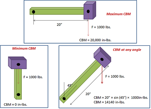
NB: In rod pumping, the CBM is expressed in thousands of inch pounds.

Continue reading

Fundamental principles of physics used in artificial lift design

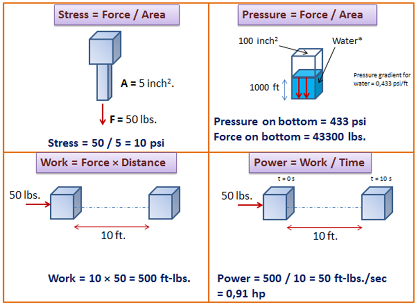
In the present article, we discuss a couple of physical quantities used in artificial lift design such as the concept of stress, pressure, work, power, energy, machine, and efficiency.

Stress is defined as force divided by area. So that, to reduce the stress you can either reduce the force or increase the cross sectional area it acts on.

Stress = Force / Area

Continue reading

Y-tool system – A solution to enable well access below ESP

The Y-tool is a solution to enable production-logging and well intervention below a working ESP at any point in time during production without pulling the completion string. The Y-tool is installed on the production tubing, providing two separate conduits. One conduit concentric with the production tubing and enables access to the reservoir below the ESP. The second conduit is offset and used to support the ESP system. Flow rates in different perforation intervals and other valuable geophysical information could be collected for production optimization and enhanced recovery plans.

With an ESP Y-tool in place, Operators are able to carry out wireline or coiled tubing logging, memory gauge deployment, tubing-conveyed perforation, well treatment and stimulation operations, effectively managing production operations and reservoir performance without pulling the ESP, dual ESP installation and bridge plug setting for water shutoff, etc.

Wireline or coiled tubing plugs can be used to seat in a nipple profile in the Y-tool to enable intervention or logging operation without retrieval of the completion. If required, the ESP can be run with these plugs in place to perform production logging or other well interventions.


Continue reading

ESP submersible pumping system

The ESP submersible pumping system consists of both downhole and surface components. The surface components are transformers, motor controllers, junction box and wellhead.

The wellhead accommodates the passage of the power cable from the surface to the wellbore.

The main down-hole components are the motor, seal, pump, and cable. Additional accessory equipment may include the gas separators, check and drain valves, cable bands and protectors, and downhole sensors.

Technologies, types, recommended practices and selection criteria of each compound of the ESP pumping system are discussed in the following list of 22 posts.

ESP Pump:

01- Submersible Pump System Overview

02- Centrifugal Pump ( ESP Pump)

03- ESP: Pump Stage

04- Pump impeller types

05- Pump Performance Curves – part 01

06- Pump Performance Curves – part 02

07- Pump Construction: Compression Pump vs. Floater Pump

08- Pump Shaft

Pump Intake:

09- Pump Intake

10- ESP Motor Shroud: Applications, Configurations and Selection Criteria

11- ESP: Gas handling device

Seal Section:

12- Motor Seal

ESP Motor:

13- ESP Motor

ESP Cable:

14- ESP Cable

15- Power losses in cables

16- Motor Lead Extension

17- ESP Power Cable Accessories

Motor Controller:

18- ESP Motor Switchboard

19- Variable Frequency Drive Basics

Transformer:

20- Introduction to transformer: How it works?

Wellhead Equipment:

21- Wellhead Equipment for ESP

Accessory Equipment:

22- ESP Accessory Equipment

Updated list of API and ISO Standards for SRP

In this article, the last updated list of API & ISO standards for sucker rod pumps is presented. These standards can be considered as reference documents as well as a basis for training classes in the subject of sucker rod pumps.


Continue reading