ESP submersible pumping system

The ESP submersible pumping system consists of both downhole and surface components. The surface components are transformers, motor controllers, junction box and wellhead.

The wellhead accommodates the passage of the power cable from the surface to the wellbore.

The main down-hole components are the motor, seal, pump, and cable. Additional accessory equipment may include the gas separators, check and drain valves, cable bands and protectors, and downhole sensors.

Technologies, types, recommended practices and selection criteria of each compound of the ESP pumping system are discussed in the following list of 22 posts.

ESP Pump:

01- Submersible Pump System Overview

02- Centrifugal Pump ( ESP Pump)

03- ESP: Pump Stage

04- Pump impeller types

05- Pump Performance Curves – part 01

06- Pump Performance Curves – part 02

07- Pump Construction: Compression Pump vs. Floater Pump

08- Pump Shaft

Pump Intake:

09- Pump Intake

10- ESP Motor Shroud: Applications, Configurations and Selection Criteria

11- ESP: Gas handling device

Seal Section:

12- Motor Seal

ESP Motor:

13- ESP Motor

ESP Cable:

14- ESP Cable

15- Power losses in cables

16- Motor Lead Extension

17- ESP Power Cable Accessories

Motor Controller:

18- ESP Motor Switchboard

19- Variable Frequency Drive Basics

Transformer:

20- Introduction to transformer: How it works?

Wellhead Equipment:

21- Wellhead Equipment for ESP

Accessory Equipment:

22- ESP Accessory Equipment

Submersible Pump System Overview

The submersible pump system consists of both downhole and surface components. The main surface components are transformers, motor controllers, junction box and wellhead. The main downhole components are the motor, seal, pump and cable. Additional downhole components may be included to the system: data acquisition instrumentation, motor lead extension, cable bands and protectors, gas separator, check and drain valves.

The following video gives a quick equipment overview of the ESP submersible pumping system:


The following figure shows schematic diagram of a submersible pump installation:

Continue reading

Step 9 – Variable Speed Submersible Pumping System

Compared to conventional ESP installations with constant motor speeds, installations running at variable frequencies have several advantages. The most important benefit of a Variable Speed Submersible Pumping System is the wide flexibility of the variable frequency ESP system that permits perfect matching of the lift capacity of the ESP system and the well’s productivity. Therefore, it operates over a much broader range of capacity, head, and efficiency.

NB: Variable Frequency Drive basics (also, named: Variable Speed Drive) are presented and discussed in the article “Variable Frequency Drive Basics”.

Since a submersible pump motor is an induction motor, its speed is proportional to the frequency of the electrical power supply. This relationship between variables involved in pump performance (such as head, flow rate, shaft speed) and power is known as “Affinity Laws” (also called “Pump Laws”).

Continue reading

Step 8 – Downhole and Surface Accessory Equipment

This article “Downhole and Surface Accessory Equipment” is the step 8 of the nine-step procedure to design an ESP with an efficient and cost-effective performance. The required downhole and surface accessory equipment are discussed and recommended practices are highlighted.

Downhole Accessory Equipment:

  • Motor Lead Extension (MLE):

API RP 11S4 defines the Motor Lead Extension as a “special power cable extending from the pothead on the motor to above the end of the pump where it connects with the power cable. A low-profile cable (flat configuration) is usually needed in this area due to limited clearance between the pump housing and the well casing”. It is recommended to select a length at least 6 ft. (1.8 m) longer than the upper end of the pump. The length of MLE has to be select in a way to avoid a splice over a tubing collar. Doing so could allow the cable to catch on the wellbore casing and damage the equipment.

  • Banding Cable Protectors:

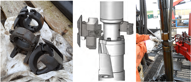
Cable protectors are used to protect the Motor Lead Cables from damage during installation, operation and pulling. The figures below show an example of cable protectors.

Continue reading

Variable Frequency Drive Basics

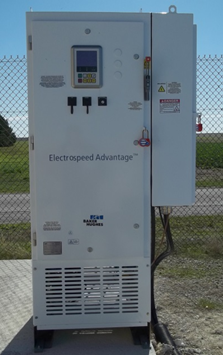
In this article, Variable Frequency Drive (also, named: Variable Speed Drive) basics are presented in a simple and easy way with explanation graphs. To understand how the Frequency Speed Controller operates, it is necessary to understand how the VSD supplies variable voltage and frequency for speed control.

The below block diagram illustration depicts a typical three-phase AC variable speed drive system. It has three main components: an Operator Control, a Drive Controller, and an AC Motor.

An Operator Control device provides a means to start and stop the motor and adjust the operating speed. The Drive Controller consists of a variety of components that work together to convert an AC input into a frequency and voltage output necessary to change the speed of an AC motor.

Main sections of a Variable Frequency Drive:

The converter section:

This section converts the incoming 3-phase AC voltage to DC voltage. The converter is essentially a 3-phase, full wave rectifier with Silicon Control Rectifiers, a specialized type of control diode, in the bridge.

The following video explains what SCR is and how it works:

Continue reading